WiFi Traffic Analysis Guide
 Arife Ebrar Üstüner
In cybersecurity operations, examining wireless network traffic at the physical layer level forms the basis of reconnaissance and threat analysis processes. This guide covers the technical stages from the process of capturing a WiFi packet over the air to the interpretation of the data.
RF (Radio Frequency): The physical medium through which data is carried via electromagnetic waves.
ISM Band: The license-free 2.4 GHz and 5 GHz frequency ranges in which WiFi protocols operate.
Monitor Mode: A mode that allows a network card to passively listen to all packets in the environment without being part of any specific network.
Beacon Frame: A management packet through which Access Points (APs) announce their presence and technical specifications to the surroundings.
Probe Request: A query packet broadcast by client devices to find networks they recognize.
RSSI (Received Signal Strength Indicator): A value measured in negative dBm representing the strength at which the receiving device hears the signal.
LNA / VGA Gain: Low-Noise Amplifier and Variable Gain Amplifier settings used during signal capture.
ANonce & SNonce: Random numbers generated during the 4-Way Handshake (A: Authenticator/AP, S: Supplicant/Client).
PSK (Pre-Shared Key): The shared password used by users to connect to the network.
PTK & GTK: Temporary keys generated at the end of the handshake used to encrypt traffic (Pairwise & Group Transient Key).
I/Q Data (In-phase and Quadrature): Two main components representing the amplitude and phase of a radio signal. SDR devices process the signal in this format to transfer it to a digital medium. (The basis of the raw data we see in URH).
Noise Floor: The natural level of electromagnetic noise present in the environment when no signal is present. For a packet to be successfully decoded, the signal strength must be above this floor.
Demodulation: The process of converting analog radio waves captured by HackRF back into digital bitstreams (0s and 1s) through software like URH.
Waterfall Diagram: A graphical representation that allows for the three-dimensional monitoring of signals in the dimensions of time, frequency, and power (color intensity).
Digital Conversion of Wireless Signals
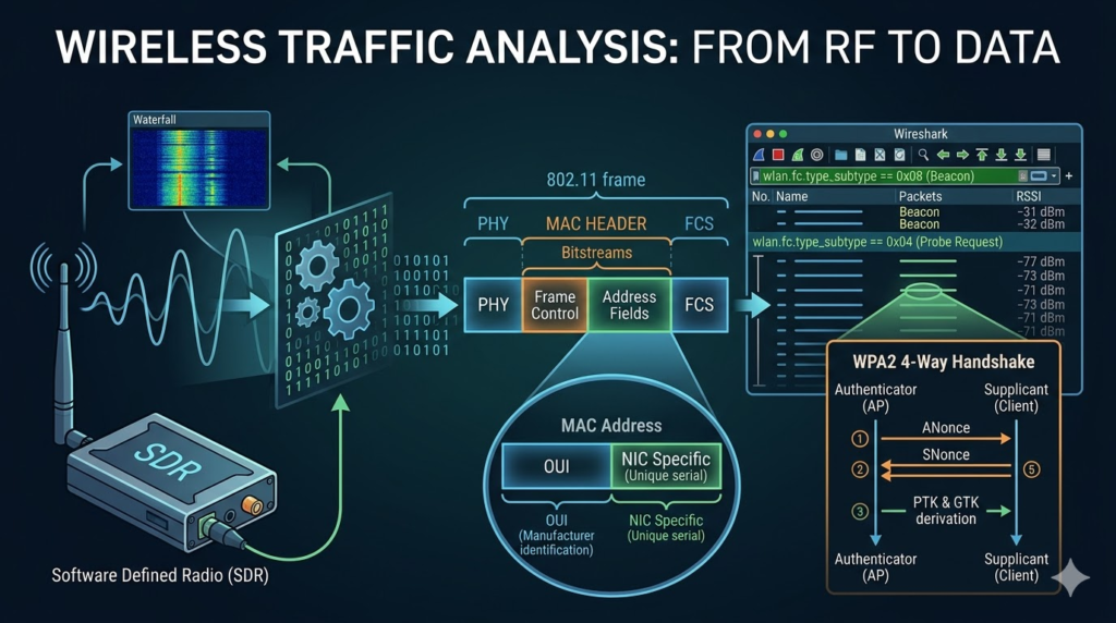
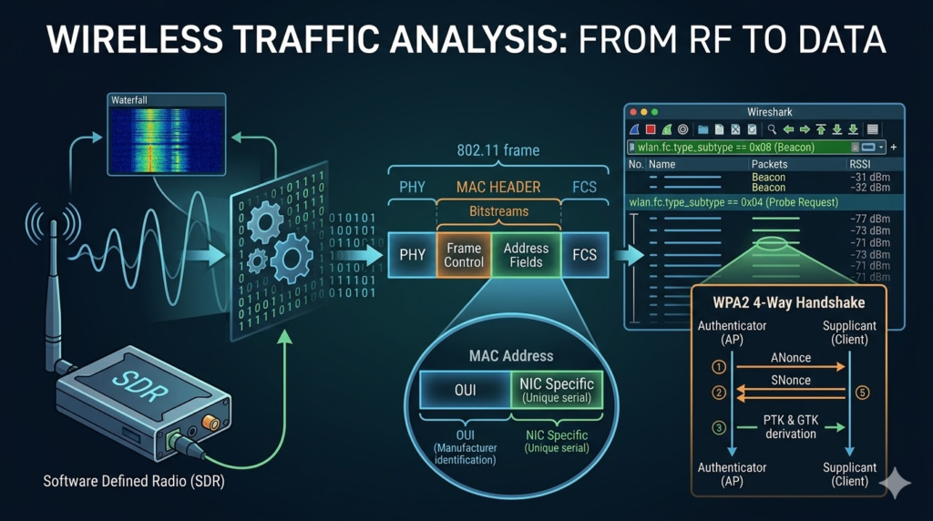
WiFi traffic propagates in the form of radio waves across the electromagnetic spectrum. A packet analysis process begins with the conversion of these analog signals into digital data through Software Defined Radio (SDR) or specialized network cards.
Monitor Mode Utilization: By setting the hardware to “Monitor Mode,” all packets on the selected channel are passively collected without the device needing to be connected to a network.
Sampling and Capture: The PortaPack H2M hardware captures raw data at the selected frequency and transfers it to digital storage units in PCAP or IQ format.
Device Preparation and Optimization
LNA/VGA Gain: Gain settings on the device must be optimized according to the environmental noise level. Excessively high gain can lead to signal distortion.
Antenna Selection: When using the PortaPack H2M, the antenna length must be adjusted appropriately for the target frequency. Incorrect antenna selection results in packet loss and inaccurate RSSI measurements.
WiFi Packet Structure (802.11 Frame)
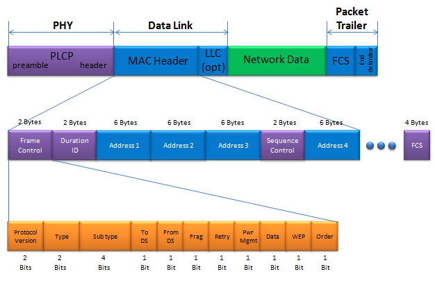
Wireless network communication is carried out through a layered structure defined within the framework of IEEE 802.11 standards.
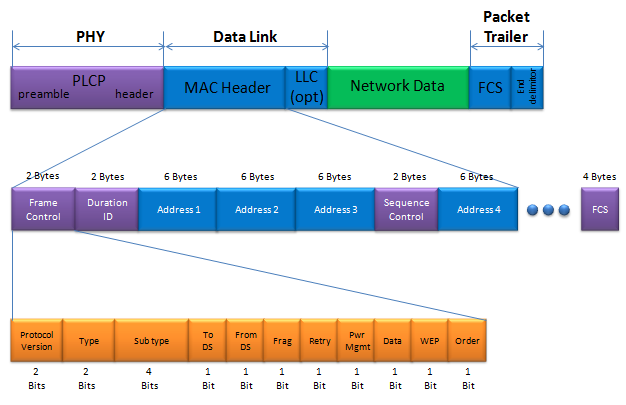
- PHY (Physical Layer): Contains the physical layer information that enables the signal to propagate through the air.
- MAC Header: The administrative center of the packet. The packet type (Beacon, Probe Request, etc.) is determined via the “Frame Control” field.
- Address Fields (1-4): In the 802.11 protocol, communication is managed through four different address fields: Receiver, Transmitter, Source, and Destination. During analysis processes, the focus is usually on the Transmitter Address (TA) data to identify which device the signal originated from.
- FCS (Frame Check Sequence): An error control mechanism that checks whether the packet was corrupted during transmission.
MAC Address Analysis and Device Identification
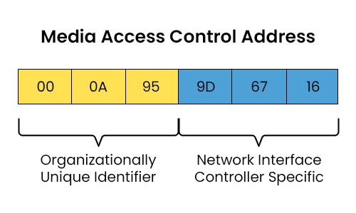
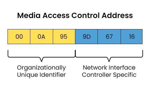
MAC addresses located in the header section of WiFi packets are physical identities that determine the source and destination of traffic on the network. They consist of two main blocks:
- OUI (Organizationally Unique Identifier): The first three-byte (24-bit) field, which is the block assigned by the IEEE to the manufacturer (e.g., Intel, Apple, or Cisco).
- NIC Specific: The last three-byte (24-bit) field, which is the unique serial number assigned to the network card by the manufacturer. It allows us to distinguish devices individually.
RSSI (Signal Strength) Parameter
RSSI (Received Signal Strength Indicator) is a measurement of how strongly the receiving device hears the incoming signal and is expressed in negative dBm (decibel-milliwatts).
- Value Ranges: Values of -80 dBm and below indicate that the signal is very weak and the risk of data loss is high. The range between -30 dBm and -40 dBm represents a cleaner interval.
- Role in Analysis: Monitoring RSSI values is used to estimate the physical location of the signal source or to understand if there is external interference (such as a jammer) in the environment. Instability in the RSSI value indicates that the signal source is in motion or that physical obstacles are attenuating the signal.
Packet Capture and Analysis Methodology
The analysis process begins by tuning the hardware (PortaPack H2M or SDR) to the relevant channel.
- Data Collection: The device is set to monitor mode, and the traffic flow is recorded in PCAP format.
- Filtering: Management frames are parsed via wlan.fc.type_subtype using tools such as Wireshark.
- Interpretation: Device identities are documented via MAC addresses in the packet headers, and the physical proximity of devices is documented via RSSI values.
Wireshark Filtering Table
| Filter Code | Description | Analysis Purpose |
wlan.fc.type_subtype == 0x08 | Beacon Frame | Lists all Wi-Fi networks (SSIDs) in the environment. |
wlan.fc.type_subtype == 0x04 | Probe Request | Identifies devices searching for a network and their MAC addresses. |
wlan.fc.type_subtype == 0x05 | Probe Response | Shows the router’s response to a device’s probe request. |
wlan.addr == [MAC] | Specific Filter | Focuses exclusively on the traffic of a specific targeted device. |
Note: New generation devices use ‘randomized MAC’ during Probe Requests for anonymity. The true hardware identity only becomes clear when the device moves to the full network connection (Association) stage.
Handshake Detection
During the analysis process, when a device’s moment of connection to the network is captured, the 4-Way Handshake process occurs, where encryption keys are derived over the air.
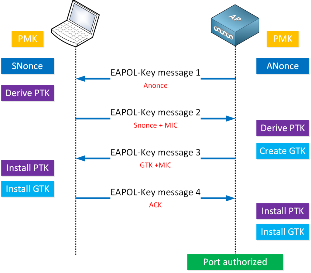
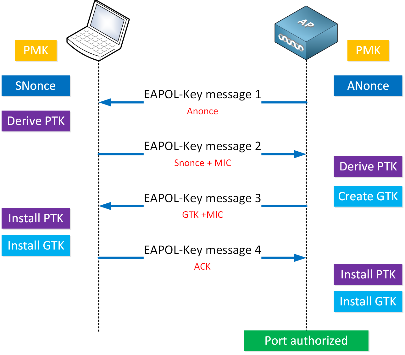
WPA2 4-Way Handshake Mechanism: In wireless network security, a secure connection between the client and the access point (AP) is established through a four-stage handshake process.
As detailed in the visual, session keys (PTK and GTK) are derived by mutually transmitting ANonce (AP side) and SNonce (Client side) values without explicitly sharing the network password (PSK) over the air. Capturing this process is mandatory for testing the password security of the network.
Ethical and Legal Standards
Wireless network analysis should only be performed in authorized testing environments. In accordance with TCK (Turkish Penal Code) No. 5237 and KVKK (Law on the Protection of Personal Data) regulations, unauthorized interference with networks is subject to legal sanctions.
Application
HackRF is not a network card, but an SDR device. The data we capture on URH and SDR# is ‘Physical Layer’ data. Our goal, rather than reading the packet content, is to analyze the physical characteristics and the raw bit structure of the signal.
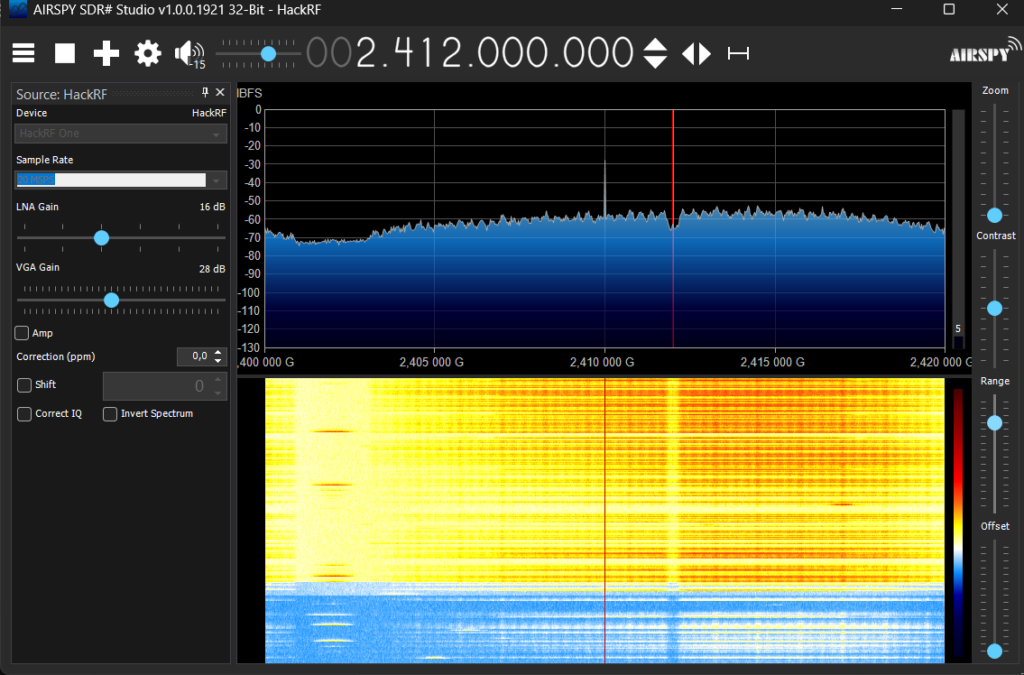
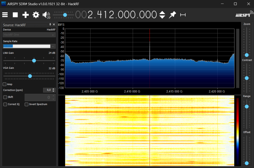
Monitoring Signals (with SDR#): We used the SDR# program. This software allowed us to visualize the radio waves captured over the air by HackRF as a graph (Waterfall). By focusing on the 2.4 GHz frequency, we clearly documented the density of WiFi packets and the signal strength through the yellow-orange bursts on the screen.
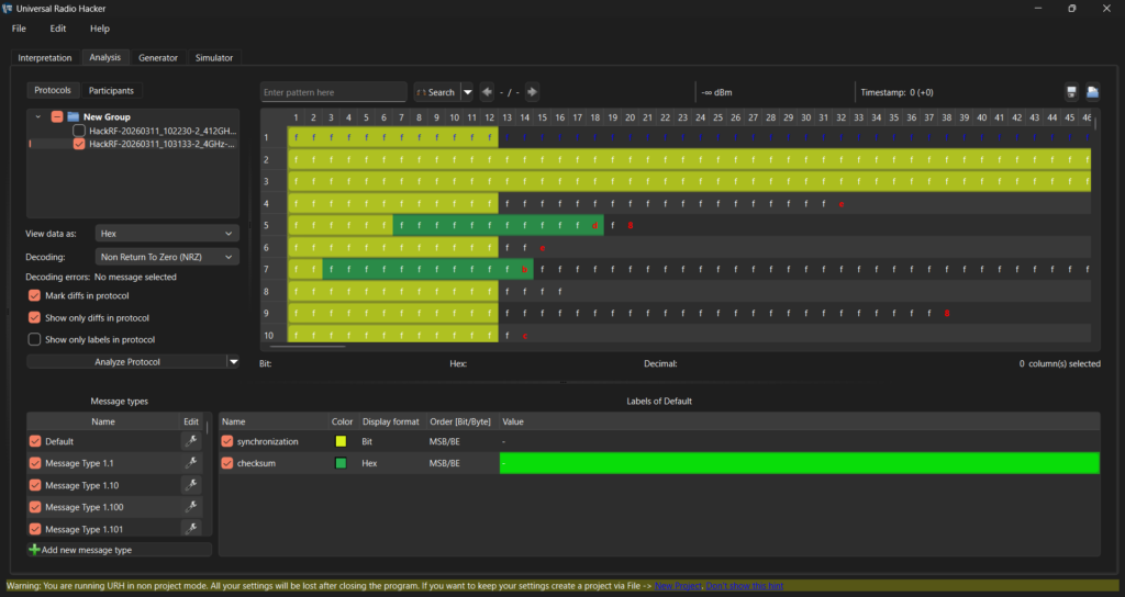
URH Analysis Process: On the URH Analysis screen, the demodulated version of the I/Q signals captured by HackRF is displayed. Each row in the table represents an independent WiFi frame over the air. The regular structure of the synchronization (Preamble) blocks as “f f f” proves that the signal was captured cleanly. The colored areas symbolize the protocol hierarchy (Header, Payload, Checksum) within the packets, and these bit-level differences are examined to identify device signatures in cybersecurity analysis.
Conclusion
In this guide, the process of capturing wireless signals from the air and converting them into digital data has been examined through SDR technology. Thanks to physical layer analysis, signal noise and raw bit sequences that conventional network cards cannot detect can be identified.
References:
- IEEE 802.11-2020 Standard: https://standards.ieee.org/ieee/802.11/7028/
- MAC Address Guidelines: https://standards.ieee.org/wp-content/uploads/2024/10/ieee-mac-address.pdf
- Wireshark User Guide: https://www.wireshark.org/docs/wsug_html/
- NetworkLessons WPA Handshake: https://networklessons.com/wireless/wpa-and-wpa2-4-way-handshake
- https://sharetechnote.com/image/WLAN_Frame_Packet_MAC.png
- https://www.pynetlabs.com/wp-content/uploads/2023/11/MAC-Address.jpeg
- https://cdn.networklessons.com/wp-content/uploads/2023/12/wpa-4-way-handshake-workflow.png
About the author
Arife Ebrar Üstüner
Signal Master
Subscribe to the newsletter
New cybersecurity articles, research and hardware-lab notes — straight to your inbox.
Related articles

MouseJack Attacks and RF Signal Analysis in nRF24L01+ Chips
Rolling Code (KeeLoq) Cryptography and RollJam Attack Architecture in Wireless Access Systems