Bit-Level Analysis of Security and Radio Frequency (RF) Signals in Wireless IoT Devices
 Akıner Kısa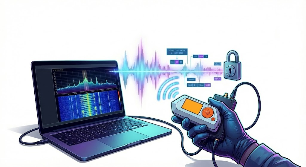
Security in wireless IoT devices is generally based on the confidentiality of the protocol structure (Security through Obscurity). However, once the RF physical layer is accessed, this confidentiality is eliminated. The aim of this research is to put into a technical framework how to analyze the bit-level structure of an unknown RF signal, how to detect coding schemes and how to perform data manipulation (Packet Injection) attacks.
TerminologyRF -> Radio Frequency
IoT -> Internet of Things
dBi -> Decibel Unit
RSSI -> Received Signal Strength Indicator – Received signal strength indicator
SNR -> Signal to Noise Ratio
SDR -> Software-Defined Radio – Software Defined Radio Communication System
CRC – Cyclic Redundancy Check
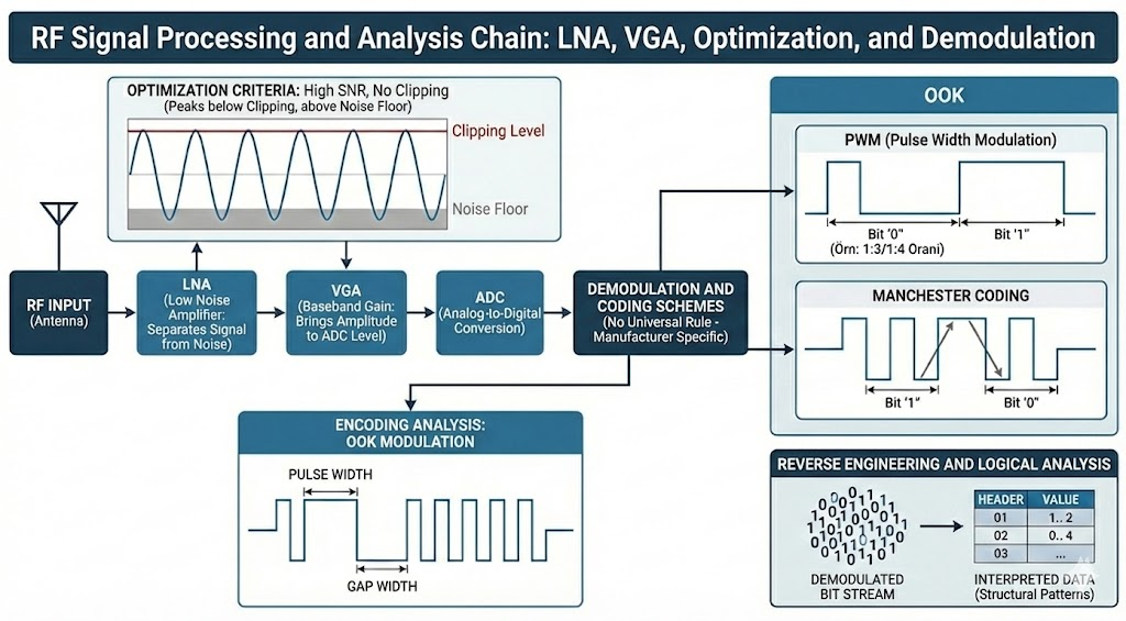
When performing RF Signal Capture and SNR Optimization (Acquisition), the success of RF analysis directly depends on the quality of the captured raw data. Fixed gain values are misleading; optimal settings must be determined dynamically according to environmental noise, the gain (dBi) of the antenna used and the strength of the target signal (RSSI).
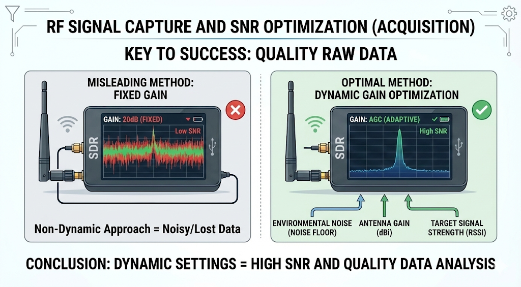
Saturation and Noise when adjusting gain on SDR hardware (HackRF One etc.) the balance of the Noise Floor should be observed.
- LNA (Low Noise Amplifier): It is applied in the first stage to separate the signal from noise.
- VGA (Baseband Gain): Increases the amplitude of the signal to ADC (Analog-Digital Converter) level. It is used to bring.
- Optimization Criteria: The target is to ensure that the peaks of the signal waveform are not clipped (without clipping) at the top where the noise floor is significantly above is to achieve high SNR value.
Conversion of analog signal to digital bits at the stage of demodulation and coding schemes is universal
It is not bound by a rule. Every manufacturer wants to reduce hardware cost or increase signal range.
It uses different coding techniques.
When performing encoding analysis, OOK (On-Off Keying) modulated signals are used as a basis two parameters are examined: Pulse Width and Gap Width.
- PWM (Pulse Width Modulation): “1” and “0” bits enable the signal to remain “High” it is determined according to the ratio of the duration. (Ex: in the Princeton protocol, the ratio is usually 1:3 or 1:4 used).
- Manchester Coding: The bit value is determined according to the transition direction of the signal in the middle of the period.
The bitstream demodulated during the reverse engineering and logical analysis phase is a pile of data unless it is interpreted. The reverse engineering process aims to reveal the structural patterns within this stack.
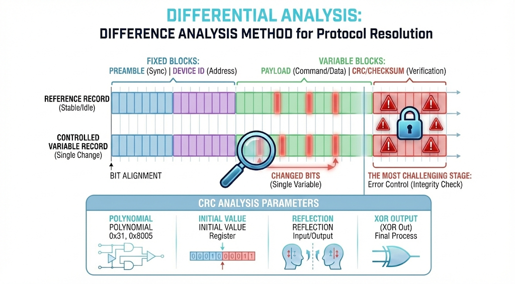
When performing Differential Analysis, the “Difference Analysis” method is applied to solve the protocol structure.
- Reference Record: The stable (idle) signal of the device is recorded.
- Controlled Variable: A single physical variable on the device (e.g. a button or sensor).
- value) is changed and the second record is taken.
- Bit Alignment: Two bit strings are aligned one under the other.
- Fixed Blocks: Preamble (Synchronization) and Device ID (Address).
- Variable Blocks: Payload (Command/Data).
The most challenging stage of Error Checking Mechanisms (CRC/Checksum) data manipulation is the recalculation of the verification value (Integrity Check) at the end of the packet. This is not just a simple addition process. CRC (Cyclic Redundancy Check) analysis should include the following parameters:
- Polynomial: Divisor value used in division (Ex: 0x31, 0x8005).
- Initial Value: The register value where the calculation starts.
- Reflection: Whether the input or output bits are inverted.
- XOR Out: The last value with which the result was XORed.
Practical Example
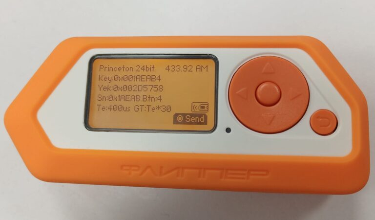
In the study conducted with Flipper Zero Princeton 24 Bit (PT2262) Simulation, in a laboratory environment Flipper Zero device instead of a physical controller to create a controlled signal source
has been used.
Research Setup
Signal Source (TX): Flipper Zero is configured to simulate Princeton (PT2262) protocol via Sub-ghz module. 24-bit fixed code packages were created manually and released periodically.
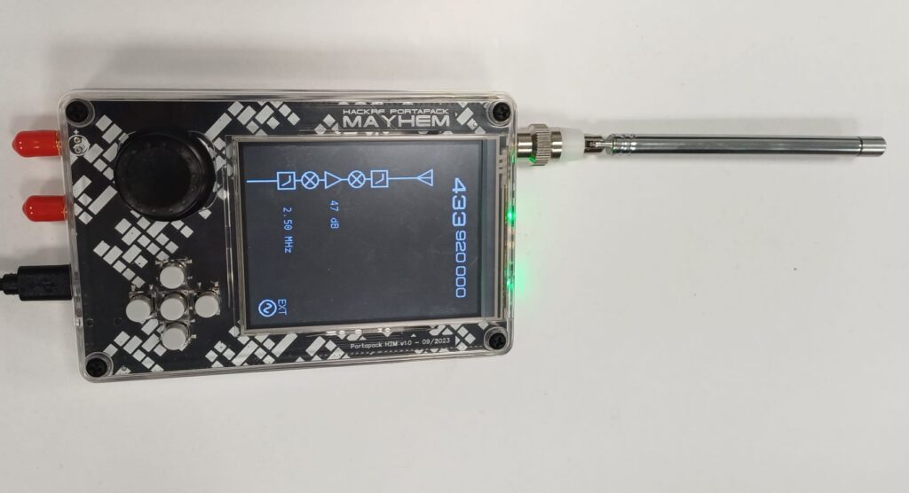
Signal Receiver (RX): HackRF One is locked to 433.92 MHz frequency with URH (Universal Radio Hacker) software. Flipper Zero frequency was captured with Universal Radio Hacker.
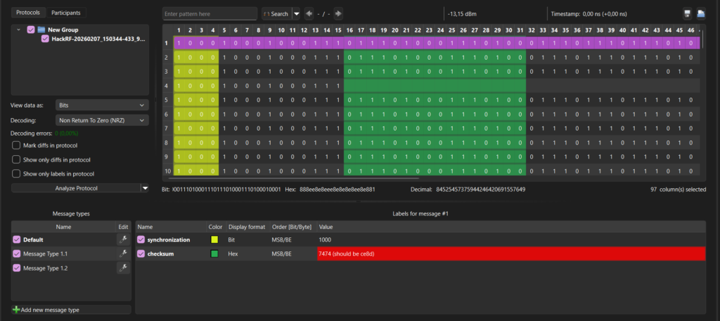
In the timing analysis of the signal produced by Flipper Zero, the structure’s standard PWM
It has been observed that it fully complies with the modulation:
Bit ‘0’: Short Pulse (α) + Long Space (3α) -> 1000 (Approx.).
Bit ‘1’: Long Pulse (3α) + Short Space (α) -> 1110 (Approx.).
We put the value of the signal record 1000100010001110111010001110100011101110111010001110100011101000111010001110111010001110100010001 into the Hex group as follows in PWM modulation: we can translate:
| Raw Signal– | –Binary Equivalent– | –Hex Group |
| PART 1 | ||
1000 | 0 | 1 |
1000 | 0 | |
1000 | 0 | |
1110 | 1 | |
| PART 2 | ||
1110 | 1 | A |
1000 | 0 | |
1110 | 1 | |
1000 | 0 | |
| PART 3 | ||
1110 | 1 | E |
1110 | 1 | |
1110 | 1 | |
1000 | 0 | |
| PART 4 | ||
1110 | 1 | A |
1000 | 0 | |
1110 | 1 | |
1000 | 0 | |
| PART 5 | ||
1110 | 1 | B |
1000 | 0 | |
1110 | 1 | |
1110 | 1 | |
| PART 6 | ||
1000 | 0 | 4 |
1110 | 1 | |
1000 | 0 | |
1000 | 0 |
Although these values vary in different cases, they generally represent approximate values.
When the captured simulation data was analyzed on Bitbench, the 24-bit data packet produced by Flipper Zero was successfully isolated:
- Address Block (Address): First 20 bits (Fixed ID).
- Data Block (Data): Last 4 bits (Command).
We decoded these values on Bitbench. In this way, we reached the key value of 1A EA B4, which is the key value of PT2262 that we simulated in Flipper Zero.
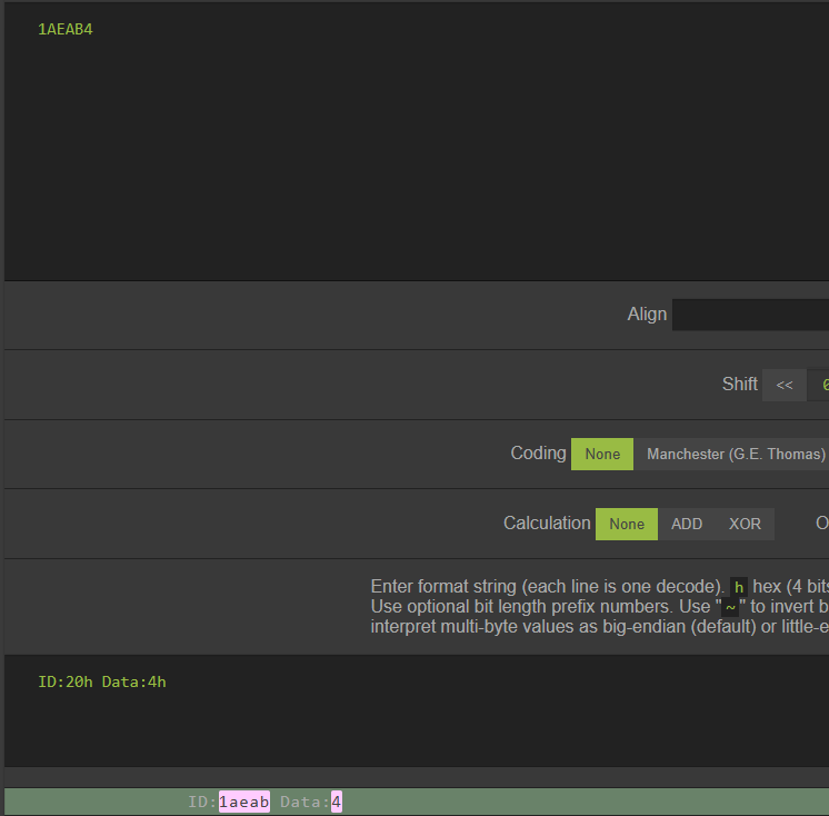
It has been verified that there is no cryptographic signature or counter in the simulated Princeton protocol, that is, it is a hard code. When the captured signal was analyzed, the key value sent via Flipper Zero was successfully reached.
Reverse engineering process; It is a multidisciplinary study that requires signal processing knowledge, protocol structure intuition and mathematical analysis (CRC) competence. This research shows that modern pentest tools such as Flipper Zero can be used both as a signal source; It has been shown that security based on the “confidentiality” principle can be easily overcome with SDR-based analysis methods.
TL;DR
This research is about the security analysis of embedded systems operating in the ISM band (433/868 MHz) and using non-standard (Proprietary) protocols. The study investigates Signal-to-Noise Ratio (SNR) optimization in the signal capture process, OOK/ASK modulated signals.
It includes demodulation techniques and analysis of complex error checking mechanisms (CRC/Checksum) that ensure data integrity. The theoretical methodology is validated by HackRF analysis performed on the simulated Princeton (PT2262) protocol using Flipper Zero as the signal source.
Sources:
https://github.com/jopohl/urh
https://github.com/triq-org/bitbench
https://github.com/AlexandreRouma/SDRPlusPlus
https://hackrf.readthedocs.io/en/latest/
https://docs.flipper.net/sub-ghz
https://cdn-shop.adafruit.com/datasheets/PT2262.pdf
https://radiolux.com.ua/files/pdf/PT2262.pdf
https://elektronikjk.pl/elementy_czynne/IC/PT2262.pdf
About the author
Akıner Kısa
Signal Master
Subscribe to the newsletter
New cybersecurity articles, research and hardware-lab notes — straight to your inbox.
Related articles

MouseJack Attacks and RF Signal Analysis in nRF24L01+ Chips
Rolling Code (KeeLoq) Cryptography and RollJam Attack Architecture in Wireless Access Systems