HackRF with Spectrum Analysis: Propagation, Polarization, and Gain Optimization
Arife Ebrar Üstüner
February 20, 20263 Minutes Read
1. Electromagnetic Wave Propagation
Radio waves propagate through the air as electromagnetic energy, and their behavior closely resembles the principles of optics. The quality of propagation depends on several physical factors:
Frequency: Lower frequency signals can reach longer distances, while high-frequency signals have a lower capacity to penetrate obstacles.
Physical Obstacles: Materials such as concrete, metal, and even the human body attenuate signal strength.
Reflection: Surrounding buildings and structures can cause signals to bounce, leading to multi-path interference.
2. Polarization and Antenna Positioning
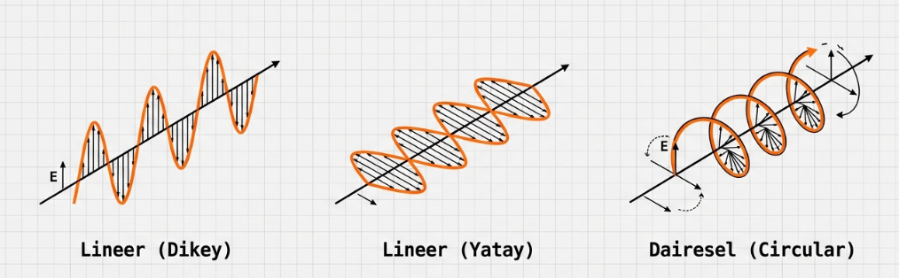
One of the most critical parameters in signal detection is polarization alignment. Radio waves have a specific direction of oscillation, and the receiving antenna must be positioned accordingly.
Polarization alignment: Keeping the transmitter and receiver antennas in the same orientation ensures maximum signal strength.
Angular Deviation: Positioning antennas at a 90-degree angle to each other (cross-polarization) causes the signal to weaken significantly or disappear entirely.
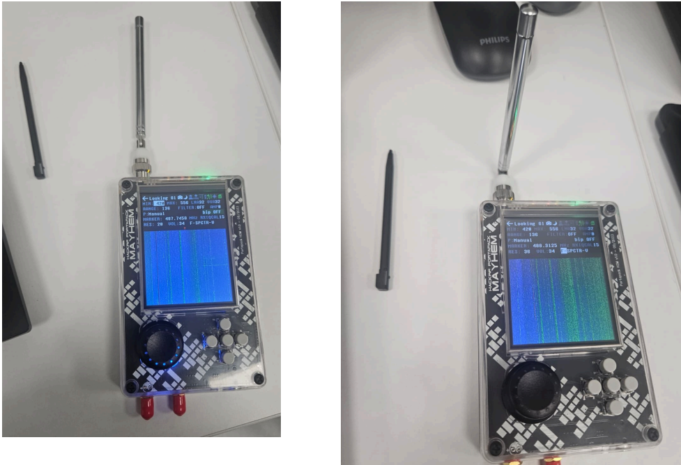
Field experiments summarize this situation:
Note: To clarify a weak signal, before diving into software adjustments, you should physically position the antenna at different angles to achieve a perfect match with the signal’s plane of propagation.
3. Gain Configuration and SNR Analysis
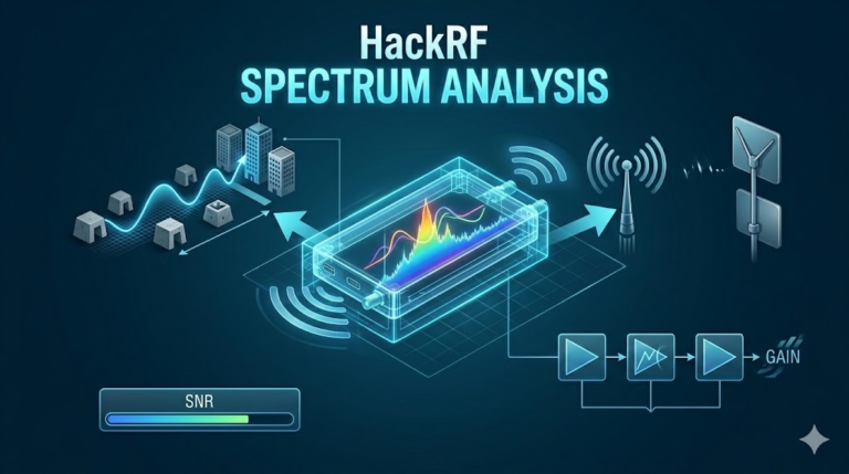
Gain settings, which increase the device’s “hearing” capacity, must be carefully balanced for signal clarity.
Gain: Think of this as increasing the HackRF’s sensitivity. However, if you push the gain too high, you amplify not only the target signal but also the surrounding noise.
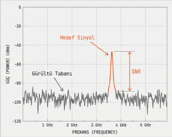
SNR (Signal-to-Noise Ratio): Our primary goal is to maintain a high SNR. A value of 30 dB or higher typically indicates a very clear signal.
There are three critical stages managing gain on the HackRF:
1. LNA (Low Noise Amplifier): The low-noise amplifier that allows you to hear the signal coming from the antenna at the initial stage.
2. VGA (Variable Gain Amplifier): The stage that amplifies the signal before processing, essentially “turning up the volume” of the signal.
3. AMP (Internal Amplifier): An internal amplifier that adds a direct +14dB to the signal; it should only be turned on as a last resort for very weak signals.
Over-increasing the gain leads to “redding out” the waterfall display and causes signal saturation. The target is never the highest gain level, but the highest SNR.
4. Power Units and Measurement (dBm)
The dBm (decibel-milliwatts) values seen on spectrum analyzers represent the actual signal power.
Value Analysis: As the value approaches 0, the signal strength increases. For example, -30 dBm represents a very strong signal, while -90 dBm indicates a weak signal.
Noise Floor: When a signal drops toward -110 dBm, it becomes nearly indistinguishable from background noise.
5. Operational Standards and Legal Regulations
To maintain technical efficiency and legal compliance, the following protocols must be observed:
Legal Limits (ISM): Although bands like 433 MHz and 2.4 GHz are reserved for unlicensed use, users must strictly comply with the output power limits defined by regulatory authorities (such as BTK).
Hardware Calibration: To minimize “ghost signals” and internal device noise, the RXIQCAL process should be performed periodically.

 Arife Ebrar Üstüner