HackRF Platform: Historical Development and Features
 Akıner Kısa
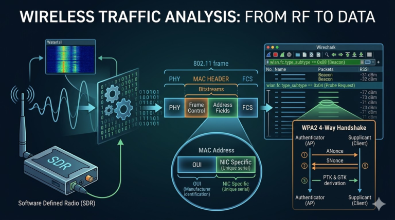
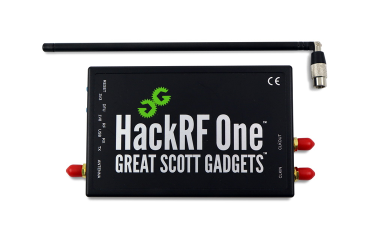
This article examines the evolution of the HackRF platform from its prototype stage to its current state, its component-level hardware architecture, and its operational capabilities, including integrations and features. It also includes comparative analyses of the platform’s menu structures, physical components, development interfaces, and its compatibility with modern multi-tools like Flipper Zero.
This article is designed as an auxiliary guide for security research activities conducted in laboratory environments and authorized settings. Activities such as listening to, interfering with, or disrupting electronic communications using a HackRF device or other methods may result in legal sanctions. Within the European Union, regulations such as the European Electronic Communications Code (EECC), and in the United States, regulations such as the Electronic Communications Privacy Act (ECPA), address the privacy of electronic communications within legal frameworks.
https://eur-lex.europa.eu/EN/legal-content/summary/european-electronic-communications-code.html
https://bja.ojp.gov/program/it/privacy-civil-liberties/authorities/statutes/1285
1. Historical Context and Platform Evolution
1.1 Origins and the Open SDR Movement
1.2 Transformation Process: From Jawbreaker to HackRF Pro
2. Hardware Architecture and Engineering Details
2.1 Core Component Analysis
2.1.1 LPC43xx Microcontroller: The Center of the System
2.1.2 RF Signal Chain and Superheterodyne Architecture
2.2 Physical Interfaces and Controls
2.2.1 Buttons and LED Indicators
3. Portable Ecosystem: PortaPack and Mayhem Firmware
3.1 PortaPack Hardware Integration
3.2 Mayhem Firmware Architecture and Menu Structure
3.2.1 Main Menu Categories
3.2.2 Receive (RX) Menu and Applications
3.2.3 Transmit (TX) Menu and Applications
3.2.4 Tools and Utilities
3.2.5 Firmware Management and Mayhem Hub
4. Computer Ecosystem for Software-Defined Operations
4.1 GNU Radio Integration and Flowcharts
4.2 SDR# (SDRSharp)
4.3 Universal Radio Hacker (URH)
4.4 Python and Scripting (libhackrf and PySDR)
5. Firmware Development and API
5.1 Libhackrf Architecture
5.2 Custom Application Development for Mayhem
6. Operational Scenarios and Hardware Extensions
6.1 Opera Cake Plugin Card
6.2 Replay Attacks and Analysis
6.3 GPS Spoofing
7. Comparative Analysis: HackRF One vs. Flipper Zero
8. Conclusion
SDR -> Software-Defined Radio
RF -> Radio Frequency
PCB -> Printed Circuit Board
IF -> Intermediate Frequency
RX -> Receive
TX -> Transmit
MCU -> MicroController Unit
API -> Application Programming Interface
IQ -> In-phase/Quadrature – A type of digital modulation used in radio broadcasting.
Half-Duplex -> Half-Duplex Communication – A system where transmission occurs in both directions but not simultaneously.
Superheterodyne -> A radio receiver architecture that uses a mixer to convert a received signal from its original carrier frequency to a stable intermediate frequency that is more easily processed.
Bias Tee -> A three-port network used to adjust the DC bias point of some electronic components without disrupting other components.
1. Historical Context and Platform Evolution
The democratization of radio technology has largely been made possible by the shift from hardware-defined to software-defined architectures. The HackRF project arose from the need for a low-cost, half-duplex transceiver capable of monitoring and interfering with signals across a wide section of the RF spectrum.
1.1 Origins and the Open SDR Movement
The HackRF project was created by security researcher Michael Ossmann, who identified a lack of affordable tools capable of monitoring and manipulating wireless signals. Prior to HackRF, SDR peripherals were either too expensive for professional use or limited to receiver (RX) capabilities, such as RTL-SDRs.
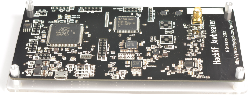
In 2014, following successful testing of a beta unit known as Jawbreaker, a Kickstarter campaign was launched for HackRF One. The project attracted attention not only for its hardware capabilities but also for its Open Source Ethics approach. Great Scott Gadgets released all design files, including KiCad schematics, PCB layout files, and firmware source code, under open licenses. This transparency allowed the community to verify the hardware integrity, modify it for specific needs, and develop third-party software support.
1.2 Transformation Process: From Jawbreaker to HackRF Pro
The hardware has undergone several iterations to improve RF performance and stability. This process includes critical milestones that have allowed the platform to mature and become an industry standard.
- Jawbreaker (Beta): The predecessor to the final product, Jawbreaker operated between 30 MHz and 6 GHz. It lacked the robust protection circuitry found in later models and used a different microcontroller (LPC4330). It also required manual modification for certain antenna configurations and included a PCB antenna.
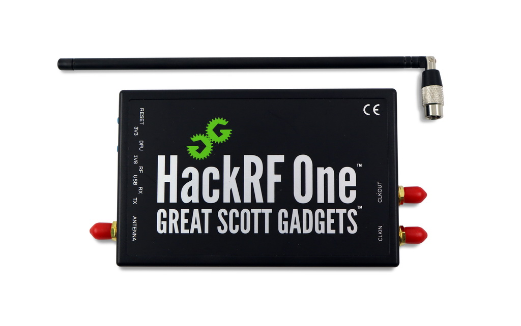
- HackRF One: This model became the production standard. It extended the lower frequency limit to 1 MHz, switched to the LPC4320 microcontroller, added a real-time clock, and integrated Reset and Device Firmware Update buttons. SMA connectors were standardized, and protection diodes were added to protect the sensitive RF front end from electrostatic discharge.
- HackRF Pro: This model was designed to address the limitations of the original design. Key improvements include a wider frequency range (100 kHz – 6 GHz), a modern USB Type-C connector, and the use of an FGPA (Field Programmable Gate Array) instead of a CPLD (Complex Programmable Logic Device) for logic operations. The Pro model also includes a TCXO (Temperature Compensated Crystal Oscillator), which solves the frequency drift issues in the original design.
2. Hardware Architecture and Engineering Details
The versatility of the HackRF One stems from the specific selection of integrated circuits (ICs) that allow for broadband operation without the need for multiple physical radios. This section presents a schematic-level analysis of the device.
2.1 Core Component Analysis
The HackRF One block diagram reveals a distributed architecture where signal processing is shared between the host and the on-board microcontroller. The table below summarizes the functions and specifications of the critical components:
| Component | Part Number | Function | Key Features |
| Microcontroller | NXP LPC4320/4330 | System Control & USB Interface | ARM Cortex-M4/M0 dual-core, 204 MHz, High-Speed USB 2.0 PHY |
| Transceiver | MAX2837 / MAX2839 | RF Modulation /Demodulation | 2.3 GHz – 2.7 GHz native operating range, WiMAX transceiver. |
| Mixer/Synthesizer | RFFC5072 | Frequency Conversion (Mixing) | 85 MHz – 4200 MHz Local Oscillator (LO), broadband mixer |
| ADC/DAC | MAX5864 | Analog-to-Digital Conversion | 22 MHz bandwidth, 8-bit resolution, transmit/receive path. |
| CPLD | Xilinx CoolRunner-II | Glue Logic & Timing | It manages the data flow between the ADC/DAC and the MCU. |
2.1.1 LPC43xx Microcontroller: The Centerpiece of the System
At the center of the board is the NXP LPC4320 (or LPC4330 in older revisions). This dual-core ARM Cortex-M4/M0 microcontroller manages USB communication with the host and enables configuration of the RF chips (via Register settings). While the 204 MHz M4 core can handle some basic signal processing tasks on the board, its primary role in standard operation is as a data pump carrying IQ samples between the USB interface and the radio hardware.
2.1.2 RF Signal Chain and Superheterodyne Architecture
HackRF achieves its wide frequency range (1 MHz – 6 GHz) through a superheterodyne architecture using the RFFC5072 mixer. This process consists of the following steps:
- Baseband Processing: The MAX5864 ADC/DAC converts digital IQ samples to analog signals (and vice versa). It naturally operates with a bandwidth of up to 20 MHz.
- Intermediate Frequency (IF): The MAX2837 (or MAX2839 in revision r9) is a broadband wireless transceiver operating in the 2.3 GHz to 2.7 GHz range. In the HackRF design, this chip functions as the Intermediate Frequency (IF) stage. Regardless of the target frequency, signals are first converted to or from this IF range.
- RF Front End: The RFFC5072 mixer upconverts or downconverts this IF signal to the desired target frequency. This architecture allows a single radio chain to cover the entire spectrum, but can cause side effects such as varying sensitivity and power output (typically between 0 dBm and 15 dBm) in different bands.
2.2 Physical Interfaces and Controls
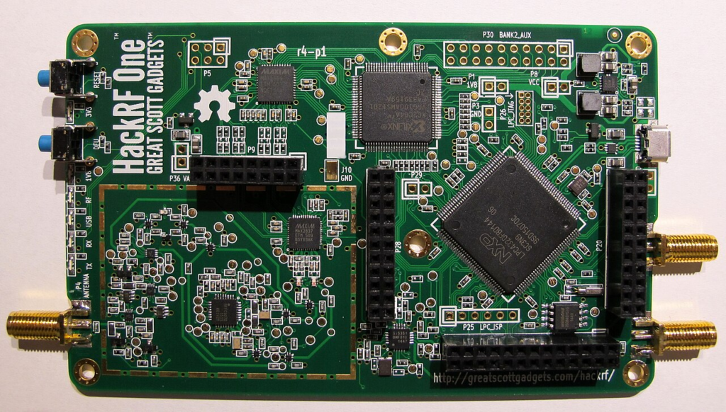
The HackRF One PCB layout is specifically designed for accessibility and expandability.
- Antenna Port: Standard SMA female connector. Includes a software-controlled Bias Tee circuit for feeding external low-noise amplifiers (LNA) or active antennas.
- Clock I/O: Two SMA connectors are used for synchronizing multiple HackRF units. A 10 MHz reference clock signal can be input to operate the internal synthesizer, or the internal clock can be passed to other devices.
- Expansion Headers: The board includes headers (P20, P22, P28) that export GPIO, I2S, and SPI interfaces. These headers allow add-ons like PortaPack to communicate directly with the MCU, eliminating USB overhead.
2.2.1 Buttons and LED Indicators
The physical user interface on the board consists of control LEDs and control buttons:
- Power and Status LEDs (3V3, 1V8, RF): Indicate the status of the various power rails. The RF LED, in particular, illuminates when the transceiver is active, physically confirming that the hardware is in broadcast or listening mode.
- USB LED: Indicates active enumeration and communication with the host.
- RX/TX LEDs: The RX (orange) and TX (red) LEDs provide immediate visual feedback about the device’s current operational mode. The red light is important for security purposes as it indicates that an active radio broadcast is in progress.
- RESET Button: Performs a hardware reset on the microcontroller and restarts the device.
- DFU Button: When held down during a reset, forces the MCU into Device Firmware Update (DFU) mode. This is a vital safety measure that allows the firmware to be recovered via a ROM-based bootloader even if the flash memory is corrupted or the device is bricked.
3. Portable Ecosystem: PortaPack and Mayhem Firmware
Although HackRF One was initially designed as a USB peripheral, the introduction of the PortaPack add-on card transformed it into a fully standalone analysis lab. Subsequent Mayhem firmware enhancements created a software layer that acted as an operating system running on this hardware.
3.1 PortaPack Hardware Integration
The PortaPack attaches directly to the HackRF’s expansion headers. It adds a touchscreen LCD display (typically 2.4 or 3.2 inches), navigation controls (directional joystick or rotary encoder/wheel), an audio output jack, and a micro SD card slot. This hardware configuration transfers the user interface workload from the computer to the device. The ARM Cortex-M4 processor on the HackRF handles basic signal processing, UI rendering, and file I/O operations, enabling autonomous operation of the device.
3.2 Mayhem Firmware Architecture and Menu Structure
The standard HackRF firmware is a simple USB bridge. Special firmware is required to use PortaPack. Havoc was a popular version in the early days, but the currently actively developed and accepted standard is Mayhem firmware. Mayhem acts like a lightweight operating system that manages the display, processes inputs, and runs customized applications for signal processing. It is file-system aware and requires a special directory structure on the SD card, such as /ADSB, /POCSAG, to store map data, frequency databases, and captured signal files.
The following section details the menu structure and tools offered by the Mayhem firmware (v2.0 and above), along with the technical functionality of each application:
3.2.1 Main Menu Categories
This menu provides access to the device’s primary operational modes. While the menu content may vary across different versions, the core functions are similar:
- Search: Signal discovery and spectrum scanning tools.
- Receive (RX): Demodulation and protocol decoding applications.
- Transmit (TX): Signal generation, simulation, and replay.
- Capture: Raw signal recording.
- Replay: Replay of captured raw IQ files. Tools: Signal analysis and system administration utilities.
- SD Card: File manager.
- Settings: Hardware configuration, calibration, and UI settings.
3.2.2 Receive (RX) Menu and Applications
This menu is central to HackRF’s analytical capabilities. Applications are separated below according to modulation type or protocol:
- Audio:
- NFM/WFM (Narrowband/Wideband FM): Receivers for radio communications (NFM) and commercial radio stations (WFM). Offers adjustable squelch and audio filtering features.
- AM: Amplitude Modulation receiver, commonly used for aviation band listening.
- SSB (Single Sideband): Demodulates USB (Upper Sideband) and LSB (Lower Sideband) signals used by amateur radio operators for long-distance communications.
- Digital Decoders:
- ADS-B: Decodes aircraft transponder signals at 1090 MHz. Displays the aircraft’s position (latitude/longitude), altitude, and ICAO codes on the screen. If map files are available on the SD card, it can visualize the aircraft’s position on a map.
- AIS (Automatic Identification System): Decodes ship tracking systems used for maritime traffic. TPMS: Reads sensor data (pressure, temperature, ID) from tire pressure monitoring systems.
- POCSAG: Displays alphanumeric messages from pager networks. This protocol is still widely used by hospitals and emergency teams.
- Radiosonde: Decodes telemetry data from weather balloons.
- BTLE (Bluetooth Low Energy): Captures advertisement packets from Bluetooth devices, lists MAC addresses and payloads.
- Visualizers:
- Analog TV: Demodulates analog video signals to create a black-and-white image on the screen.
- SSTV (Slow Scan TV): Decodes the image transmission protocol over audio frequencies used by amateur radio operators and draws the image on the screen.
- New Features (v2.2.0):
- WeFax Receiver: Receives weather fax maps transmitted over HF bands.
- NOAA APT Receiver: NOAA (National Oceanic and Atmospheric Administration) decodes APT (Automatic Picture Transmission) signals from weather satellites to create satellite images.
3.2.3 Transmit (TX) Menu and Applications
This menu is used for signal injection and test broadcasts.
Warning: The use of these features is subject to local radio frequency laws and should only be done in isolated (Faraday cage) environments or on licensed bands. The security of electronic communications is protected by law.
- Signal Generators:
- Microphone: Broadcasts audio using the audio jack on the PortaPack with NFM, WFM, or SSB modulations. Functions as a simple radio transmitter.
- Morse Code: Automatically converts and broadcasts text input into CW (Continuous Wave) Morse code.
- Burger Pager: Simulates the protocol of disc-shaped pagers used in restaurants.
- Replay Attacks:
- OOK (On-Off Keying): Simulates OOK signals, commonly used in simple remote controls.
- Key Fob: Emulates captured Sub-GHz control signals (e.g., garage doors). Note: Modern systems’ “Rolling Code” technology often blocks simple repeat attacks, but the tool is critical for analyzing these protocols.
- Jamming/Interference (Theoretical/Lab Use):
- Jammer: Programmable noise or tone generator. Used to block a specific frequency range.
3.2.4 Tools and Utility Programs
- Spectrum Painter: Converts an image file (bitmap) into a frequency spectrum that can be displayed on a waterfall screen.
- Signal Generator: Generates pure sine waves or modulated test tones.
- Antenna Length: A calculator that determines the optimum antenna length (quarter wave, half wave) based on the target frequency.
- SD Card Wipe: A tool for securely erasing data from an SD card.
- Level: A tool that graphically monitors signal strength at a specific frequency over time.
3.2.5 Firmware Management and Mayhem Hub
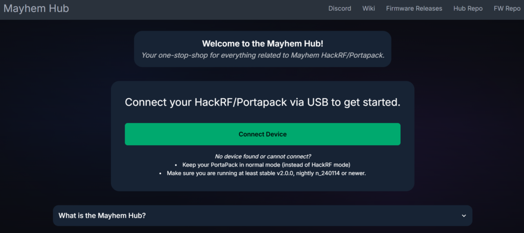
Mayhem firmware updates, which previously required complex command-line operations, are now web-based via the Mayhem Hub (hackrf.app). This tool uses WebUSB technology to flash the device directly through a Chromium-based browser without the need for any driver installation. Additionally, the on-device HackRF Mode application disables the PortaPack interface, transforming the device back into a standard USB peripheral and allowing computer control.
4. Computer Ecosystem for Software-Defined Operations
When PortaPack is not used, or for analyses requiring higher processing power, HackRF One is used by connecting it to a computer. It can transfer high-bandwidth IQ data at up to 20 million samples per second (20 MSPS) via USB 2.0.
4.1 GNU Radio Integration and Flowcharts
GNU Radio is the industry standard framework for signal processing development and has native compatibility with HackRF One.
- Source/Sink Blocks: The primary interface blocks are
osmocom Source(for RX) andosmocom Sink(for TX).- Device Arguments: Users use the parameter
hackrf=0(or serial number if there are multiple devices) to address the card. - Sample Rate: Adjustable up to 20 MHz, but the 2-10 MHz range is generally more stable to prevent data loss.
- Gain Settings: Three gain stages must be managed:
RF(Amp, 0/14dB),IF(LNA, 0-40dB), andBB(VGA, 0-62dB). These settings are critical for optimizing the signal-to-noise ratio (SNR).
- Device Arguments: Users use the parameter
- Flowgraph Structure: A typical FM receiver flowgraph includes the following blocks:
osmocom Source(set to ~100 MHz).Low Pass Filter(for isolating the channel).WBFM Receive(Demodulation process).Audio Sink(for transmitting audio to computer speakers). This modular approach allows researchers to visually construct complex demodulators for satellite communications, GSM, or custom protocols.
4.2 SDR# (SDRSharp)
For Windows users, SDR# is the most popular GUI-based tool for visual exploration.
- Installation: Replaces standard Windows USB drivers with the “WinUSB” driver using the Zadig tool, providing direct access to the hardware.
- Plugins: HackRF integrates with a controller plugin that directly displays LNA, VGA, and Amp gain sliders on the side panel. The waterfall display allows for visual detection and quick identification of signals before moving on to complex analyses.
4.3 Universal Radio Hacker (URH)
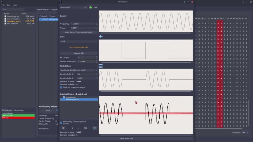
URH, which runs on Windows, Linux, and macOS, is a GUI tool focused on the analysis and reverse engineering of wireless protocols.
- Installation: Can be installed on Windows using a portable package or pip. HackRF directly recognizes RTL-SDR and similar SDR devices; additional driver configuration is usually not required.
- Features: URH supports operations such as bit-level analysis by recording signals, extracting protocol structure, and manipulating packets. It offers an analysis panel showing bit/symbol analysis, timing, and repetition patterns instead of a waterfall display.
- Interaction: It integrates with HackRF, allowing management of recording, analysis, and replay processes from a single interface. It is particularly suitable for quickly modeling unfamiliar protocols.
4.4 Python and Scripting (libhackrf and PySDR)
For automation and custom analytics, the libhackrf library provides Python bindings. PySDR is a key resource for developing Python-based SDR tools and offers tutorial examples for directly processing IQ data. Scripts are used to implement automated scanning, burst detection, or custom frequency hopping algorithms that are difficult to configure in GUI-based tools.
5. Firmware Development and API
For advanced developers, HackRF offers in-depth customization options with its C-based API and open-source firmware.
5.1 Libhackrf Architecture
libhackrf is the host-side C library that enables communication with the device. It provides the low-level functionality needed to develop custom SDR software.
- Basic Functions:
hackrf_init()/hackrf_exit(): Initializes and closes the library.hackrf_open(): Retrieves the device handle.hackrf_start_rx(callback): Starts the asynchronous data stream. The user must provide a callback function that processes the incoming IQ sample buffer.hackrf_set_freq(),hackrf_set_sample_rate(): Hardware configuration commands.
- Data Format: The library transmits data as consecutive 8-bit signed quadrature samples (I, Q, I, Q…). Developers must convert these to floating-point complex numbers for most signal processing mathematics.
5.2 Custom Application Development for Mayhem
Developing applications for PortaPack (Mayhem) involves writing C++ applications that run on ARM Cortex-M4.
- Toolchain: Requires the ARM GCC compiler and CMake. The build system creates a .ppfw (firmware binaries) or external .ppapp files.
- UI Framework: Mayhem provides a widget-based UI library. Developers use the View, Button, Text, and Painter classes to create interfaces on small LCD screens.
- Signal Processing: Real-time processing is limited by the clock speed of the M4 processor. Therefore, optimization is usually done using fixed-point arithmetic or lookup tables instead of heavy floating-point mathematics.
6. Operational Scenarios and Hardware Expansions
6.1 Opera Cake Add-on Card
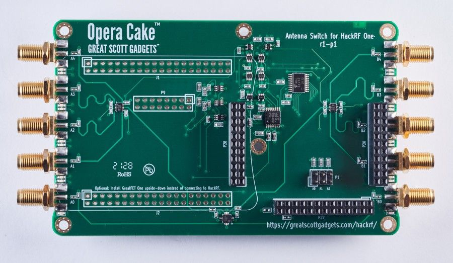
Opera Cake is a dedicated add-on board designed to expand the physical capabilities of the HackRF One. Mounted directly onto the HackRF, this board acts as an antenna switching matrix.
- Functionality: Includes two primary ports and eight secondary ports. Can be configured as 1×8 switch (one radio, eight antennas) or two 1×4 switches.
- Usage Scenarios:
- Automatic Testing: Switching between antennas optimized for different frequency bands without manual cable switching.
- Direction Finding: Applying pseudo-Doppler or sector switching techniques by quickly switching between directional antennas to determine the angle of arrival of the signal.
- Filter Banks: Routing the signal through external physical filters (High-pass, Low-pass) connected to secondary ports to improve signal purity.
6.2 Replay Attacks and Analysis
With PortaPack, HackRF can capture and replay a raw signal. Unlike different devices that decode and reproduce the signal, HackRF records and plays back the raw physical radio waves as they are. This feature is extremely powerful for testing receiver tolerances when the full protocol is unknown or when analyzing Rolling Code behavior.
6.3 GPS Spoofing
HackRF’s transmitter (TX) capability allows it to simulate GPS signals. Using software like gps-sdr-sim, a fake GPS coordinate file (IQ data) can be created and broadcast via HackRF. This causes nearby GPS receivers to believe they are in a different location.
Warning: This procedure is strictly prohibited outside of laboratory settings as it may jeopardize aviation and maritime safety and is subject to severe legal penalties.
7. Comparative Analysis: HackRF One vs. Flipper Zero
One device frequently compared to HackRF is the Flipper Zero. While both devices play an important role in research, their fundamental purposes and applications are radically different. HackRF is a laboratory environment, while Flipper Zero is a Swiss Army knife that can be used for various tests.
| Feature | HackRF One (with PortaPack) | Flipper Zero |
| Primary Function | Broadband Software-Based Radio | Multi-Protocol Hardware Tool |
| Frequency Range | 1 MHz ile 6 GHz (Uninterrupted) | Sub-1 GHz (300-928 MHz), 13.56 MHz (NFC), 125 kHz (RFID) |
| Bandwidth | 20 MHz instant | Narrowband (CC1101 transceiver limits) |
| Modulation Support | Unlimited (Software defined: AM, FM, SSB, Digital, Private) | Fixed (Hardware limited: ASK/OOK, FSK, GFSK) |
| Analytical Ability | Raw IQ capture, waterfall visualization, complex protocol solving | Predefined protocol repetition, simple frequency analysis |
| Connection | High bandwidth to computer via USB | USB, Bluetooth, GPIO, Infrared |
| NFC / RFID | No (Requires external hardware) | Built-in (Native 13.56 MHz / 125 kHz hardware) |
| Target Audience | RF Engineers, Signal Intelligence, Researchers | Pentesters, Physical Security Inspectors, Hobbyists |
Flipper Zero is optimized for interaction with common consumer technologies (RFID cards, garage doors, NFC tags). Its use of the CC1101 transceiver chip limits it to specific modulation schemes and bandwidths. HackRF One, on the other hand, is a raw instrument. It captures the radio spectrum in its raw form. This allows it to analyze high-bandwidth signals that Flipper cannot physically “see,” proprietary protocols outside of standard ISM bands, or satellite downlinks. However, HackRF lacks the built-in NFC/RFID/Infrared hardware convenience offered by Flipper. Therefore, both devices have different use cases and capabilities depending on the situation.
8. Conclusion
In conclusion, HackRF remains the defining platform for radio frequency research. Its value lies not only in its hardware capabilities (1 MHz – 6 GHz tuning and 20 MHz bandwidth) but also in the comprehensive ecosystem growing around it. The compatibility between open-source hardware, the PortaPack portable interface, and the Mayhem firmware creates an equally capable tool environment in both static lab settings and permitted field environments. While next-generation tools like Flipper Zero offer ease of use for specific tasks, HackRF One is a professional standard providing raw, unfiltered access to the radio spectrum necessary for in-depth technical research and development.
TL;DR
This article examines the evolution of the HackRF platform from prototype to mature product level, detailing its hardware architecture, RF signal chain, and core components. The integration of PortaPack and Mayhem firmware transforms HackRF into a portable, standalone analysis tool; menus, applications, and operational capabilities are explained in detail. The computer-based processes using the GNU Radio, SDR#, URH, and Python ecosystems, as well as firmware development processes using the libhackrf API, are discussed. Hardware extensions like Opera Cake, replay attacks, GPS spoofing, and laboratory scenarios are presented, along with a comparative evaluation against Flipper Zero.
Sources
https://en.wikipedia.org/wiki/HackRF_One
https://docs.flipper.net/zero
https://www.rs-online.com/designspark/hands-on-with-hackrf
https://hackrf.readthedocs.io/en/latest/index.html
https://greatscottgadgets.com/hackrf/
https://greatscottgadgets.com/sdr/
https://static.chipdip.ru/lib/841/DOC052841344.pdf
https://allthewriteups.gitbook.io/book/rf-hacking/101/hackrf-one-101
https://www.scribd.com/document/737709802/HackRF-One-User-Manual
https://wiki.mexle.org/_media/laborausstattung/hackrf_one_tutorial_f2017_-_report.docx.pdf
https://hackerwarehouse.tv/product-category/general-rf/assembly-guide/
https://github.com/portapack-mayhem/mayhem-firmware
About the author
Akıner Kısa
Signal Master
Subscribe to the newsletter
New cybersecurity articles, research and hardware-lab notes — straight to your inbox.
Related articles

MouseJack Attacks and RF Signal Analysis in nRF24L01+ Chips
Rolling Code (KeeLoq) Cryptography and RollJam Attack Architecture in Wireless Access Systems